Modernizing Drafting Conventions for Interdisciplinary Clarity
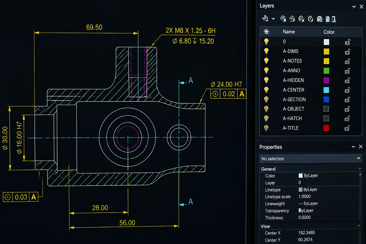
The updated CAD Layer and Line Weight Standards establish a unified graphical language across architectural, structural, mechanical, electrical, and civil disciplines. Complex contract drawings require unmistakable visual hierarchy. When drawing packages combine contributions from multiple sub-consultants, uncoordinated layering structures create unreadable sheets, misaligned plotting line weights, and extended field verification cycles.
This update refines the standard layer naming syntax based on the United States National CAD Standard (NCS v6.0) and ISO 13567 principles, while modernizing plot style tables (CTB and STB) to maintain crisp legibility on both high-density digital displays and large-format plotted sheets.
Standardized Layer Naming Syntax
The standardized layer schema employs four core data fields separated by hyphens. Adherence to this taxonomy ensures instant automated filtering and clean external reference (XREF) overlay management:
- Discipline Designator (1-2 characters): Identifies the primary authoring field (for example,
Afor Architecture,Sfor Structural,Mfor Mechanical,Efor Electrical,Cfor Civil). - Major Group (4 characters): Specifies the primary building system or drawing element (such as
WALL,DOOR,FLOR,HVAC,POWR,ANNO). - Minor Group (4 characters, optional): Subdivides the major element by specific function or material (such as
FULL,PRTN,IDEN,TEXT,DIMS). - Status Modifier (1 character): Classifies phase or demolition state (
Nfor New,Efor Existing to remain,Dfor Demolition,Ffor Future work).
A typical example for an interior architectural drywall partition is A-WALL-PRTN-N. This syntax allows every team member to isolate, freeze, or restyle drawing components across all project viewports without ambiguity.
Harmonized Line Weight Hierarchy and Pen Mappings
Visual hierarchy in technical documentation relies on calibrated line weight progression. The updated standard defines seven primary pen weights mapped consistently across color-dependent plot styles:
- Extra Thin (0.13 mm / 0.005 in): Surface hatching, subtle material patterns, grid line centerlines, and distant background context.
- Thin (0.25 mm / 0.010 in): Dimension lines, extension lines, leader lines, text callouts, minor equipment outlines, and secondary annotations.
- Medium (0.35 mm / 0.014 in): Standard doors, window frames, non-structural casework, plumbing fixtures, and general architectural components.
- Bold (0.50 mm / 0.020 in): Primary cut lines for interior non-bearing walls, structural framing outlines, major equipment boundaries, and title block borders.
- Heavy Bold (0.70 mm / 0.028 in): Exterior building envelope cut lines, primary structural columns in plan view, and major section cutting planes.
- Extra Heavy (1.00 mm / 0.039 in): Matchlines, property boundaries, critical safety zoning, and large-scale detail cut indicators.
Screening and Halftone Layer Protocol
Existing conditions and background structural grids must provide clear geometric orientation without overpowering new design scope. The update establishes dedicated screening percentage classes:
Existing background elements assigned to layers with the -E modifier use a 50% screen tint by default. Distant civil topography or site bounds use a 30% screen tint. New structural or MEP equipment overlays placed over architectural backgrounds remain at 100% solid opacity with standard line weights, eliminating visual collision during coordination reviews.
Implementation and Quality Audit Procedures
Drafting teams must incorporate the updated standard templates (DWT files) into daily production pipelines. Prior to publishing any sheet package for formal review or tender issuance, lead drafters must execute automated layer audit scripts to detect unassigned layers, purge orphaned blocks, and confirm that all entity properties are set to ByLayer rather than hardcoded entity colors.
Frequently Asked Questions
Why is ByLayer enforcement mandatory across all drawings?
Hardcoding specific color or line weight overrides on individual entities prevents global layer management and disrupts external reference styling. When properties are set to ByLayer, project leads can adjust entire sheet appearances uniformly across hundreds of sheets in seconds.
How does this standard handle legacy existing building surveys?
Legacy survey files are imported into dedicated C-TOPO-LEG-E or A-FLOR-LEG-E layers and locked in read-only background layers. Any surveyed element modified during new construction is migrated to the active -N or -D layer naming protocol.